Black Friday•30% off annual plans•Win an iPad + Apple Pencil•Ends in --d --:--:--•Black Friday•30% off annual plans•Win an iPad + Apple Pencil•Ends in --d --:--:--•Black Friday•30% off annual plans•Win an iPad + Apple Pencil•Ends in --d --:--:--•Black Friday•30% off annual plans•Win an iPad + Apple Pencil•Ends in --d --:--:--•Black Friday•30% off annual plans•Win an iPad + Apple Pencil•Ends in --d --:--:--•Black Friday•30% off annual plans•Win an iPad + Apple Pencil•Ends in --d --:--:--•Black Friday•30% off annual plans•Win an iPad + Apple Pencil•Ends in --d --:--:--•Black Friday•30% off annual plans•Win an iPad + Apple Pencil•Ends in --d --:--:--•
Black Friday•30% off annual plans•Win an iPad + Apple Pencil•Ends in --d --:--:--•Black Friday•30% off annual plans•Win an iPad + Apple Pencil•Ends in --d --:--:--•Black Friday•30% off annual plans•Win an iPad + Apple Pencil•Ends in --d --:--:--•Black Friday•30% off annual plans•Win an iPad + Apple Pencil•Ends in --d --:--:--•Black Friday•30% off annual plans•Win an iPad + Apple Pencil•Ends in --d --:--:--•Black Friday•30% off annual plans•Win an iPad + Apple Pencil•Ends in --d --:--:--•Black Friday•30% off annual plans•Win an iPad + Apple Pencil•Ends in --d --:--:--•Black Friday•30% off annual plans•Win an iPad + Apple Pencil•Ends in --d --:--:--•
Your plan already holds the perspective. Every horizontal dimension in the finished drawing — the width of each bay, the gap between mullions, how far the wing recedes — is sitting in that plan waiting to be projected. You do not need to guess any of it, and the reason your freehand attempts keep collapsing is that you have been guessing all of it.
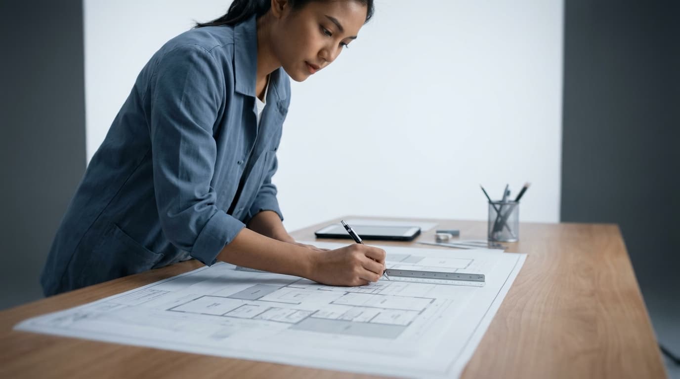
So stop sketching and start constructing. Tape the plan to the top of your board, rotated to the angle you want to view the building from. The perspective gets drawn underneath it. That single arrangement — plan above, perspective below, sharing the same vertical lines — is the whole method, and it is what the course calls the constructive or descriptive-geometry approach rather than intuitive freehand drawing. Slower. Honest. Repeatable.
Rotate the Plan, Then Draw the Line That Decides Everything
With the plan taped down at your chosen rotation — say 30 degrees to one face, 60 to the other — draw a horizontal line across the board touching the nearest corner of the building. That is your picture plane in plan: the imaginary transparent sheet the 3D space gets projected onto.
Make it touch a corner. Not near it. Touching.
That contact point is the most valuable thing on the board, because anything lying in the picture plane is drawn at true scale. If your plan is at 1:100, the vertical line you drop from that corner can be measured at 1:100 straight off your elevation. Every other height in the drawing is derived from it. Move the plan back off the picture plane and you lose your only free measurement, which is why so many student constructions end up with a building of indeterminate size.
The Station Point Is Not Where You Feel Like Standing
Below the picture plane line, somewhere on the board, you place the station point — the eye. In plan it is a single dot, and it is the thing that controls distortion. Not the vanishing points. Them you no longer choose at all.
As a rule of thumb we use in practice: put the station point back far enough that the whole building sits comfortably inside your natural field of view. A workable test is to pull it back until the distance from the station point to the picture plane is around twice the overall width of the building as measured along the picture plane. Closer than that and the near corner starts to splay open like a fisheye lens. Further back and the drawing flattens towards an elevation, which is dull but never wrong.
Also check where the dot sits left to right. Centre it roughly on the part of the building you want the reader to look at. Shunt it to one side and the far wing stretches like chewing gum.
Vanishing Points: Found, Not Placed
Everybody tells you to put the vanishing points "as far apart as possible". That is not a method, it is a shrug. With the plan up there you can find their true positions in about fifteen seconds.
From the station point, draw a line parallel to one face of the building until it hits the picture plane line. Mark it. Draw a second line from the station point parallel to the other face, hit the picture plane, mark it. Those two marks are your vanishing points. Drop them vertically onto your horizon line below, and that is where they belong — no further apart, no closer.
This is exactly what David demonstrates in the course when answering a question about constructing a view from given dimensions and a 30/60 rotation: parallels from the station point give you the vanishing points on the picture plane, and you take them down into the perspective view. The maths is done by the geometry. You just hold the set square steady.
Rotate the plan more towards one face and watch that vanishing point run away off the board while the other comes galloping in. That is the trade you are making every time you choose a view angle, and seeing it in plan is far more instructive than any amount of theory.
When the Vanishing Points Are Off the Board
They usually are. A reasonable rotation on a reasonable building throws at least one vanishing point a metre or more past the edge of the paper, and this is the point at which most people quietly give up and start eyeballing.
Three ways to deal with it, all of which work:
Pin and thread. Push a drawing pin into the table or an extension strip of card taped to the board at the vanishing point, loop a length of non-stretch thread over it, pull taut and use it as the straightedge guide. Lay your pencil against the thread. Crude, fast, accurate enough for a drawing.
A trammel. Strip of stiff card with a pin hole at the vanishing point end and a pencil slot at the other. Swings cleanly, holds the geometry, costs nothing.
Scale the construction down. Do the plan-above setup on a smaller sheet, record the angle each receding line makes to the horizontal with a protractor, then redraw those angles at full size. Less elegant, but it keeps everything on one table.
What you need on the desk for all of this: a T-square or parallel motion, two set squares, a long straightedge, a scale rule, masking tape, and pins. If you want the longer argument about kit, our guide to sketching tools and materials covers it. Nothing here needs anything exotic.
Eye Height Comes Off Your Section, Not Out of the Air
Now the perspective itself. Draw the ground line low on the sheet, then the horizon line above it at your eye height, measured at the drawing scale off your own section or elevation. Standing adult eye level is roughly 1.5 to 1.6 metres — at 1:100 that is a horizon line about 15mm above the ground line. Tiny. It always looks wrong to beginners and it is always right.
Which surfaces you see follows directly, and the course drills this with a box on a table: anything below the horizon shows you its top, anything above shows you its underside, and anything the horizon cuts through shows you neither. If you have drawn a canopy at 3m and you can see its upper surface, your eye height is lying.
Then drop that true-height vertical from the corner touching the picture plane. Mark the ground floor level, the cill heights, the head heights, the eaves — all measured off your elevation at drawing scale, all on that one line. From each mark, rule back to the appropriate vanishing point. You now have the entire height system of the building, correctly diminishing, from one measured line.
Horizontals Come Down Through the Rays
Here is the part the freehand tutorials cannot give you, because they have no plan.
From the station point, draw a visual ray to every corner, jamb, mullion, column and step edge on the plan. Where each ray crosses the picture plane line, drop a vertical straight down into the perspective. That vertical is where the element lives, in perspective, horizontally. Cut it top and bottom against the receding height lines you just ruled from the true-height line.
That is it. Plan gives you across, elevation gives you up, the picture plane is the hinge between them.
It is laborious for a façade with forty openings, so two shortcuts earn their keep:
Diagonals halve anything. The diagonals of a receding rectangle cross at its true centre in perspective. Vertical through the crossing, and you have the midpoint of a bay, a door in the middle of a wall, the ridge of a gable. Repeat to get quarters.
The sliding repeat for equal bays. Construct the first bay properly from the plan. Find the midpoint of its far vertical using the diagonals. Then rule a line from the top of the near vertical, through that midpoint, and carry on until it meets the bottom receding line. Where it lands is the next vertical. Repeat from there and the bays keep diminishing at exactly the right rate, indefinitely, without another projection. For an irregular rhythm you go back to the rays — but for a colonnade or a window run, this is the trick that saves the afternoon.
Check It Against the Plan Before You Ink Anything
The advantage of this setup is that verification is free. Pick a point you did not project — the far corner of a bay window, a chimney, the end of a wall. Project it now. If the vertical lands where your drawing already put it, the construction holds. If it misses by 3mm, something upstream has slipped, and you want to know that before you have spent two hours on brick hatching.
Second check: every horizontal edge on the building must head to one of your two vanishing points, no exceptions, unless the roof is pitched — in which case it gets its own vanishing point on a vertical through the main one. As the course puts it when working through shadows, not all vanishing points need to sit on the horizon line. Sloping planes have their own, and so does the sun.
The Three Things That Make a Student Perspective Read as Wrong
Eye height set too high. It is the commonest fault by a distance, because a higher horizon shows more of the building and feels more generous. It also turns your view into a photograph of a model. If you are drawing a person's view, put the horizon at a person's eyes and accept that you will not see the roof.
Vanishing points too close together. This is a station point problem, not a vanishing point problem, and no amount of nudging the points later will fix it. Pull the eye back in plan and reconstruct.
Figures at uncontrolled scale. If everyone is standing on the same flat ground and your eye height is standing height, then every standing figure's head touches the horizon line, near or far. Only their feet and their width change. Get that one rule right and a crowd scales itself. Then keep the proportions honest — the course splits the figure in half at the hip, the top half into thirds with the head as the uppermost third, the lower half into two for the legs.
Only now do you add weight to the lines, drop the shadows, and populate it. Shading an inaccurate drawing does not rescue it; it just makes the error more expensive. Geometry first, atmosphere second, and in that order the drawing will hold up to anyone who puts a scale rule on it.