The Drawing Nobody Wants to Do (But Every Project Needs)
Most foundation detail drawing errors aren't structural miscalculations. They're communication failures — drawings that leave contractors guessing at the exact junctions where guessing is most expensive. The concrete gets poured, the DPC ends up in the wrong place, the insulation stops six inches short of where it needed to continue, and nobody finds out until the building is up and the energy assessor is asking awkward questions.
By the end of this article, you'll know what an architectural foundation detail drawing must show, which foundation type to reach for on which project, where the thermal envelope breaks down and why, and how to avoid the ten most common errors that trip up even experienced architects. This applies to real project types — residential extensions, new-build commercial, conservation work — not abstract theory from a textbook nobody reads.
An architectural foundation detail drawing must convey soil bearing capacity, frost depth, DPC position, and insulation continuity as a minimum to satisfy UK building regulations in 2026. Get those wrong and you haven't just drawn a bad detail — you've created a liability.
A complete architectural foundation detail drawing includes five information layers: geometry, materials, dimensions, annotations, and cross-references to the structural engineer's specification. Miss any one of them and the detail fails — not structurally, but as a communication document.
The geometry layer is the obvious one — the shape of the foundation, the wall above it, the floor construction meeting it. Materials layer: every element named, with product references where the spec requires them. Dimensions: not approximate, not 'to SE's requirements', but actual numbers — or an explicit cross-reference to where those numbers live. Annotations: FFL, EGL, bearing depth, DPC position, frost line, cavity closer. Cross-references: the structural engineer's drawing number, the specification clause, the energy assessor's modelled junction.
The non-negotiable information layers
In the UK, the frost line for foundation design is typically set at a minimum of 450mm below external ground level under Approved Document A. That number needs to be on the drawing. Not implied. Not 'refer to SE'. Shown.
Finished floor level relative to external ground level is another non-negotiable. It sounds obvious. It is consistently missing from foundation details produced by architects at every experience level. If you can't read the relationship between FFL and EGL from the section, you can't read the DPC position, you can't verify the step-down in sloping sites, and you can't check the threshold detail at the door. One dimension, enormous consequences.
What building regs require vs what good practice demands
Approved Document A sets the structural floor — bearing depth, foundation width relative to wall load. Approved Document C covers moisture — DPC, DPM, ground contamination. Approved Document L covers thermal performance — insulation continuity, psi-values at junctions. Each document sets a minimum. Good practice means your detail satisfies all three simultaneously, in a single coherent drawing, without contradiction.
The difference between a structural engineer's detail and an architect's detail
The architect's foundation detail and the structural engineer's foundation detail serve different purposes — the architect coordinates junctions and thermal continuity; the engineer specifies bearing capacity and reinforcement. The SE draws loads, bar sizes, concrete grades, and bearing depths. The architect draws how the foundation meets the wall, how the insulation wraps the junction, where the DPC sits, how the cavity closes. These are two different drawings that must agree with each other. When they don't — and they frequently don't — the contractor has to make a decision on site. That decision is rarely the right one.
Strip, Pad, Raft: Pick the Right Foundation Before You Draw Anything
Strip foundations are the standard choice for UK residential masonry construction on ground with a bearing capacity of at least 75 kN/m², typically 600mm wide and a minimum of 450mm deep. They are the workhorse of domestic construction, the default assumption, and the most likely thing you'll draw on any residential project.
But drawing the wrong type — or drawing a type before the SE has confirmed ground conditions — is one of the most time-consuming mistakes you can make. Confirm first. Draw second.
Strip footings — the residential workhorse
Under a standard 150mm cavity wall on stable ground, a strip footing is typically 600mm wide and cast in mass concrete at a minimum 1:3:6 mix. The depth varies with bearing stratum — the 450mm frost-line minimum is a floor, not a target. On clay-heavy sites, you may be looking at 900mm or deeper. The drawing must show the actual depth to bearing, not a generic minimum.
Trench fill is the mass concrete variant — the trench is filled almost to ground level rather than leaving a void for brickwork below DPC. Faster to construct on stable ground, simpler to draw, and the main annotation is bearing depth and concrete mix specification.
Pad foundations — when loads concentrate
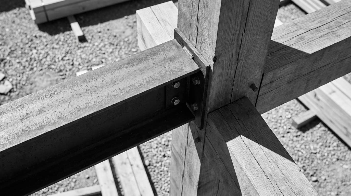
Pad foundations are used under concentrated point loads such as steel columns or timber posts — the architectural detail must show the column base connection and any holding-down bolt arrangement. The SE designs the pad — size, depth, reinforcement. The architect draws the interface: the base plate, the bolt pattern, the grout bed, the waterproofing where the column penetrates any floor construction. These are the things the SE drawing doesn't show. They matter.
Raft slabs — poor ground, big footprint
Raft foundations are most appropriate on shrinkable clay soils common across much of southern England, where differential settlement risk makes strip or pad foundations unsuitable. The section must show edge thickening, insulation below slab, DPM position, and how the upstand connects to the wall above. Raft details are more complex to draw than strip details — the thermal continuity challenge is particularly acute because the insulation runs beneath the entire slab and must connect to the wall without a break.
Pile caps — when you're drawing above the problem
The architect draws the pile cap, not the pile. The pile is the SE's domain. Your drawing shows the cap geometry, the ground beam connection, and the interface with the floor construction above. On constrained urban sites and brownfield plots, pile caps are increasingly common. The coordination requirement with the SE is higher than any other foundation type.
Foundation Type
Typical Application
UK Soil Suitability
Minimum Drawing Requirements
SE Coordination Level
Thermal Complexity
Foundation TypeStrip Footing
Typical ApplicationResidential masonry walls
UK Soil SuitabilityStable ground, bearing ≥75 kN/m²
Thermal bridging at the foundation-to-wall junction is one of the five most significant sources of heat loss in UK new-build residential construction, and it originates as a drawing error before it becomes a construction defect. The insulation stops. There's a gap. Concrete conducts heat straight out of the building. The SAP model shows a psi-value that the actual construction doesn't achieve. The building fails to perform as designed.
This is not a niche problem. It is endemic.
Where heat escapes at the foundation junction
The junction between ground floor insulation and wall insulation is where most architects draw a gap — literally and thermally. The floor insulation runs to the edge of the slab. The wall insulation starts at the cavity above. Between them: a strip of concrete, a strip of blockwork, and nothing. That gap is a thermal bridge. It shows up on thermographic surveys. It contributes to condensation risk. It costs the occupant money every winter.
UK Building Regulations Part L requires architects to calculate and declare psi-values for key thermal bridge junctions, including the ground floor edge detail. The Approved Document L Appendix contains linear thermal transmittance values for standard junction types — but if your detail doesn't match those standard types, you need a calculated value. That means your drawing needs to be accurate enough for an energy assessor to model it.
Drawing the insulation correctly — floor, wall, and the awkward bit in between
The correct detail wraps perimeter insulation down the inner face of the foundation, connecting to floor insulation, connecting to wall insulation — an unbroken thermal envelope. Draw it with a continuous line. If that line breaks anywhere, you have a thermal bridge.
Practical test: take any foundation section you've drawn and trace the insulation layer with a red pen. If the line breaks, find out why, and fix it before the drawing leaves your desk.
For under-slab use, Kingspan Kooltherm K103 Floorboard has a compressive strength of 140 kPa, making it one of the strongest PIR insulation options for residential foundation details in 2026. EPS is cheaper and widely used, but has lower compressive strength — adequate for most domestic loads, but check against the SE's slab loading. XPS offers better moisture resistance, which matters on sites with high water table risk.
Conservation projects: when you can't insulate the way you want to
Solid floors, breathable construction, lime mortars — the thermal strategy changes completely in conservation work. You cannot simply wrap PIR insulation around a historic masonry foundation without risking moisture entrapment and accelerated decay. In heritage contexts, wood fibre board or cork insulation are the materials of choice — vapour-open, compatible with lime, and acceptable to conservation officers. The thermal performance is lower, but the building survives.
If you want to practise drawing these junctions correctly — in Revit and AutoCAD, with real annotation conventions — the ArchAdemia Architectural Detailing course covers ground floor details, wall junctions, and the coordination workflow between architect and structural engineer.
Waterproofing, DPC, and the Drawing That Keeps Water Out
Under UK Approved Document C, the damp-proof course must be positioned a minimum of 150mm above external finished ground level — this dimension must be explicitly shown on every architectural foundation section drawing. Not indicated. Not implied by the drawing scale. Dimensioned. With a leader. With the words '150mm min above EGL' written on it.
This is one of the most commonly mislabelled elements in foundation details. It is also one of the most inspected by building control.
DPC position — it's not where most people draw it
The DPC sits at least 150mm above external ground level. That means external ground level needs to be clearly shown on the drawing too — as a dimension, not just as a line. If the ground slopes, show the worst-case point. If there's a step down at a threshold, show how the DPC negotiates it. The DPC is not a detail you can approximate. It is a building regulations requirement with a specific dimension, and that dimension must be legible on the drawing.
DPM position under slab is a separate question. Above the insulation, the DPM is protected from puncture during construction but sits in a warmer zone — which affects condensation risk. Below the insulation, it's more vulnerable to damage but provides better protection against ground moisture rising through the slab. Both positions are used in practice. What matters is that the drawing shows which one you've chosen, and that it's consistent with the specification.
Basements and tanking: a different drawing problem entirely
BS 8102:2009 defines three grades of basement waterproofing: Grade 1 (some moisture tolerated), Grade 2 (no moisture tolerated), and Grade 3 (dry environment required) — the architect must specify and draw the appropriate type. Type A is a barrier system — tanking applied to the structure. Type B is structurally integral — the concrete itself is the waterproofing. Type C is a drained cavity system — water gets in, but is managed and removed. Each type has a different drawing convention, a different specification, and a different maintenance implication. Specify the grade, specify the type, draw the detail, and cross-reference the spec. All four.
Ground contamination and radon: when the detail has to do more work
In high-radon areas of the UK — including most of Devon, Cornwall, and parts of Northamptonshire — foundation details must incorporate a radon-resistant membrane and, in high-risk zones, a sub-slab ventilation void. Check the BGS radon map before you draw. If the site is in a Radon Affected Area, the detail changes. The membrane specification changes. The sub-slab void, if required, needs to be shown with its dimensions and ventilation path.
On brownfield sites, ground gas and contamination may require a gas-resistant membrane specification. This changes the DPM entirely — standard polythene is not sufficient. Annotate every membrane with its BS/EN standard reference. It protects you professionally and it gives the contractor the information they need to specify correctly.
Comparison Table: Foundation Types at a Glance
(See full table in the Strip, Pad, Raft section above — structured for quick reference and cross-comparison across all five foundation types.)
Try This on Your Next Project
A complete architectural foundation detail drawing passes a 10-point audit covering foundation type, bearing depth, DPC position, DPM position, insulation continuity, FFL/EGL relationship, cavity closer, radon/gas protection, structural cross-reference, and material annotations. Run this audit on any detail before it leaves your desk.
The five-minute foundation detail audit
Take an existing foundation detail — yours, a colleague's, one from a previous project. Work through this checklist:
Foundation type named and dimensioned — strip, pad, raft, trench fill, pile cap. Named on the drawing, not just implied by the geometry.
Bearing depth shown and referenced to SE's spec — an actual dimension, with a cross-reference to the structural engineer's drawing number.
DPC at 150mm above EGL — dimensioned — not indicated, not scaled off, dimensioned with a leader note.
DPM position shown — above or below insulation, clearly indicated, consistent with the specification.
Insulation shown with product reference and thickness — not just a hatched zone. Named product, stated thickness, stated thermal conductivity where required.
Thermal continuity traceable — trace the insulation layer with a pen. If it breaks, the detail has a thermal bridge.
FFL and EGL both shown with levels — both as dimensions and as datum references.
Cavity closer position shown — where the cavity closes at the foundation, and what closes it.
Radon/gas protection referenced — if the site requires it, the membrane is specified and shown.
This checklist is the drawing that gets you through a building control inspection without a phone call. It applies to residential construction — commercial projects add fire compartmentation at ground floor, plant room waterproofing, and access floor considerations. Conservation projects add breathability requirements, lime compatibility, and heritage officer sign-off.
For students and junior architects learning to produce these details in Revit or AutoCAD, ArchAdemia's architectural detailing course works through foundation sections, wall junctions, and roof details with real annotation conventions and coordination workflow. The AutoCAD Complete Guide and Revit Beginner course both cover the drawing setup you need to produce details at the right scale and with the right layer structure.
FAQ: Foundation Detail Drawing
What is an architectural foundation detail drawing?
An architectural foundation detail drawing is a large-scale section (typically 1:20 or 1:10) showing how a building's foundation connects to the floor construction and wall above it. It must show foundation type and dimensions, DPC position, DPM, insulation continuity, FFL and EGL, and cross-references to the structural engineer's specification. It is a coordination document, not a structural calculation.
What scale should a foundation detail drawing be drawn at?
Foundation details are typically drawn at 1:20 for general arrangement and 1:10 for critical junctions such as the DPC position or insulation continuity. In Revit, detail views are set up independently from model views — the model geometry provides the base, and detail components and annotations are added at the appropriate scale. AutoCAD details are typically drawn at 1:10 in model space and scaled on the sheet.
What is the minimum depth for a foundation in the UK?
Under Approved Document A, the minimum depth for a strip or trench fill foundation in the UK is 450mm below external ground level — the frost line threshold. On clay soils or sites with trees, the minimum is significantly greater, often 900mm to 1.5m, to account for shrinkage and heave risk. The structural engineer determines actual bearing depth based on ground investigation data.
Where should the DPC be positioned in a foundation detail?
The DPC must be positioned a minimum of 150mm above external finished ground level under Approved Document C. This dimension must be explicitly shown on the drawing as a dimensioned annotation — not implied by scale. The DPM beneath the slab is a separate element and its position (above or below insulation) must also be clearly indicated.
What is the difference between a strip foundation and a trench fill foundation?
A strip foundation leaves a void between the bottom of the concrete and ground level, allowing masonry to be built up below DPC. A trench fill foundation fills the trench almost entirely with mass concrete, bringing the concrete to just below ground level — faster to construct, less vulnerable to trench collapse, but uses more concrete. Both are suitable for residential masonry on stable ground with bearing capacity of at least 75 kN/m².
When should a raft foundation be used instead of strip footings?
Raft foundations are used on shrinkable clay soils, sites with poor or variable bearing capacity, or where differential settlement risk makes strip footings unsuitable. Much of southern England sits on shrinkable clay — the Building Research Establishment's guidance and the structural engineer's ground investigation report will confirm whether a raft is required. The architectural section for a raft is more complex than a strip, requiring edge thickening, sub-slab insulation, and careful DPM positioning.
What does BS 8102:2009 require for basement waterproofing?
BS 8102:2009 defines three grades of basement waterproofing protection: Grade 1 allows some moisture and is suitable for car parks and plant rooms; Grade 2 requires no moisture and suits workshops and storage; Grade 3 requires a dry environment and applies to habitable spaces. The architect must specify the appropriate grade and draw the corresponding waterproofing type — barrier (Type A), structurally integral (Type B), or drained cavity (Type C).
Do I need to show radon protection on a foundation detail?
Radon protection is required on foundation details for sites in Radon Affected Areas as defined by the British Geological Survey radon map. In basic protection zones, a radon-resistant membrane is required. In full protection zones, a sub-slab ventilation void is required in addition. Devon, Cornwall, and parts of Northamptonshire are among the highest-risk areas. Always check the BGS map before finalising the foundation detail specification.
Foundation details are where the gap between architectural intention and built reality is smallest — and where the consequences of that gap are largest. The drawing is unglamorous, it won't win you a design award, and it's rarely the thing anyone asks to see in an interview portfolio. But it is the drawing that determines whether the building performs as designed, whether the contractor can build it without phoning you, and whether building control signs it off without a site visit.
Draw it properly. Every time. If you want structured practice on exactly these details — annotated, coordinated, and drawn in the tools you actually use — ArchAdemia's detailing course is the place to start.