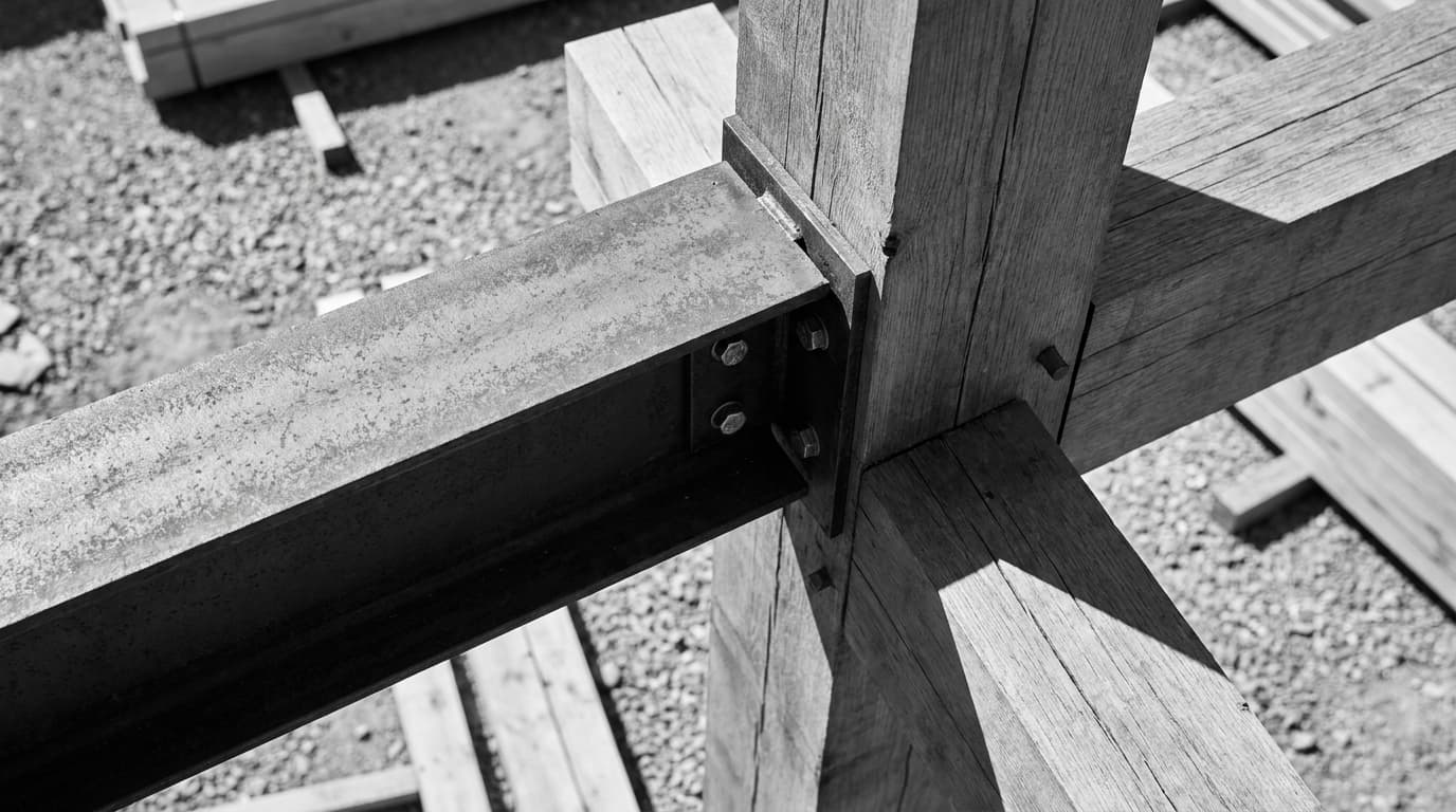
Foundation details are the most consequential drawings on any project, and they receive the least design attention until something goes catastrophically wrong on site. An architectural foundation detail drawing must show bearing level, formation level, DPC position, insulation continuity, and the relationship between structural and finished floor levels — without these, the detail is incomplete and uncoordinated. Most foundation-related site queries stem from architects producing details that show the structural element but omit the building fabric, leaving contractors to guess at insulation, DPC, and floor build-up coordination.
This article covers exactly what a compliant, buildable foundation detail drawing must contain — across strip, pad, raft, and pile cap foundation types, and across residential, commercial, and conservation contexts. Requirements differ between these types, but the coordination principles are consistent. Get them right and your detail package sails through building control. Get them wrong and you're fielding RFIs from site at 7am on a Tuesday.
What a Foundation Detail Drawing Actually Is (And Isn't)
An architectural foundation detail drawing is distinct from a structural engineer's foundation drawing — the architect's detail shows the building fabric, insulation, DPC, and floor build-up coordination; the engineer's drawing shows the concrete element dimensions and reinforcement. These are two different documents serving two different purposes. The problem is that architects frequently treat them as interchangeable, or worse, defer entirely to the engineer and produce nothing coordinated at all.
The Architect's Scope Versus the Structural Engineer's Scope
The structural engineer sizes the foundation — depth, width, reinforcement, bearing capacity. That's their job. The architect's job is to coordinate everything that wraps around it: the wall build-up, the floor construction, the insulation, the moisture control layers, and the interface between all of them. When those two outputs aren't coordinated on a single drawing, you get thermal bridges, DPC omissions, insulation discontinuity, and a building control officer with a red pen and a lot of questions.
Building Regulations Parts A, C, and L all impose requirements on foundation details — a drawing that satisfies structure but ignores thermal continuity or moisture control is non-compliant regardless of how accurate the concrete dimensions are. Part A covers structural integrity. Part C covers moisture resistance. Part L covers thermal performance. Your foundation detail must satisfy all three simultaneously, and it's the architect's responsibility to show that it does.
Why 'The Engineer Will Sort It' Is the Most Expensive Sentence in Architecture
Thermal bridging at the wall-floor junction is among the most commonly flagged issues at building control in residential projects. That's not a structural failure — it's a coordination failure. The engineer produced a perfectly adequate concrete detail. The architect assumed the thermal information would sort itself out. It didn't. Now there's a remediation cost, a delay, and a contractor asking whose fault it is.
The four foundation types covered here — strip, pad, raft, and pile cap — all share this coordination problem. The specific challenges differ, but the principle is the same: the architectural detail must show the complete picture, not just the bit the engineer hasn't already drawn.
The Non-Negotiable Information Every Foundation Detail Must Include
Every architectural foundation detail drawing must include: finished floor level, structural floor level, formation level, bearing depth, DPC position and lap with DPM, insulation type and continuity, blinding specification, and external ground level — all dimensioned and annotated. These are not optional extras. These are the minimum. If any one of them is missing, the detail is incomplete.
Levels, Levels, Levels
Five levels must appear on every foundation detail: finished floor level (FFL), structural floor level (SFL), formation level, bearing level, and external ground level. Each must be annotated with a datum reference — typically shown as a relative dimension in millimetres from a site benchmark. Absolute levels matter for setting out. Relative levels matter for coordination on site, and it's the relative dimensions that contractors actually use.
The gap between FFL and external ground level isn't just a number — it determines where the DPC sits, whether you need a step at the threshold, and whether your floor insulation thickness is achievable within the structural zone. Get this dimension wrong on the drawing and every other element cascades.
The Moisture Control Layer — DPC, DPM, and Where They Meet
The DPC in the wall and the DPM under the slab must be shown connecting or lapping on the detail drawing — an unconnected DPC and DPM creates a moisture bridge that Building Control will flag and contractors will miss. Under UK Building Regulations, the DPC must be positioned a minimum of 150mm above external finished ground level — this dimension must be explicitly shown and annotated on the foundation detail. It sounds basic. It's missed constantly.
The DPM should be shown running continuously under the slab and turning up to lap with the DPC in the wall. The lap dimension — typically a minimum of 100mm — should be annotated. The DPM gauge should be specified (typically 1200 gauge polyethylene for residential). None of this appears on the engineer's drawing. All of it must appear on yours.
Thermal Continuity: Closing the Loop at the Wall-Floor Junction
Show insulation position, thickness, and continuity. At strip foundations, floor insulation must return vertically against the inner leaf to prevent cold bridging. This is the element most frequently omitted from architectural foundation details, and it's the one that generates the most building control queries. The Accredited Construction Details (ACDs) published by the government provide benchmark junction details — they're the reference point BCOs use, and they should be the reference point you use when drawing.
Specify the insulation type and its lambda value. Specify the thickness. Show where it starts, where it ends, and what happens at the junction between horizontal and vertical runs. If you're using a proprietary system, reference the manufacturer's detail and note the thermal performance figure.
Structural Bearing and Formation Level
Show the bearing depth below formation, the blinding layer (typically 50mm weak mix concrete or compacted hardcore), and the relationship between the structural element and the ground conditions noted in the site investigation. If the site investigation has flagged variable ground, the detail should note the contingency — deeper bearing, lean mix backfill, or engineer's instruction on site. This isn't over-engineering the drawing. It's protecting yourself when the groundworker hits something unexpected at 900mm depth.
Strip, Pad, Raft, Pile Cap: What Changes Between Foundation Types
While the mandatory elements remain constant, each foundation type introduces specific coordination challenges that must be shown on the architectural detail. The information doesn't change — the geometry and the sequencing do.
Strip Foundations: Residential Bread and Butter
Strip foundations are the most common foundation type in UK residential construction, and the most common source of avoidable RFIs. The key issues: stepped foundations on sloped sites (show each step clearly with dimensions related to internal floor level), cavity insulation continuity below DPC level, and the relationship between inner leaf blockwork and the top of the concrete.
On a sloped site, the stepped strip detail is where things fall apart. Each step must be dimensioned — both the vertical rise and the horizontal run — and related back to the internal FFL. The DPC must be maintained continuously at 150mm above external ground at every step. Draw every step. Don't assume the contractor will figure out the geometry.
Pad Foundations: The Commercial Workhorse
Pad foundations appear in commercial and framed structures, where point loads from columns are transferred to the ground through isolated concrete pads. The key coordination tasks: showing the column base plate or starter bars (which the structural engineer will detail but which must be located relative to your finished floor level), the relationship between the pad and the ground-bearing slab, and movement joints at the pad perimeter.
The movement joint at the pad perimeter is the most commonly missed element. The ground-bearing slab must be isolated from the pad to allow differential movement — if it's not shown on the architectural detail, it won't get built. The structural engineer's drawing shows the pad. Your drawing shows the slab, the joint, and the floor build-up around it.
Raft Foundations: When the Ground Can't Be Trusted
Raft foundation details must show the insulation position (above or below the structural slab), the perimeter upstand dimension, and the threshold detail where the raft meets external paving or landscaping. Rafts are used on poor ground, filled sites, or where differential settlement is a risk — contexts where the threshold condition is particularly important because external ground levels may change over time.
The insulation position is a design decision with significant thermal implications. Insulation above the slab (floating floor) is thermally efficient but reduces structural floor-to-ceiling height. Insulation below the slab (inverted) simplifies the slab construction but requires careful detailing at the perimeter. Whichever you choose, show it explicitly, dimensioned, with the perimeter upstand shown in relation to external ground level.
Pile Caps: Coordination at Its Most Demanding
Pile cap foundation details require the architect to produce a coordinated detail showing the suspended floor build-up, thermal envelope, and ventilation void — elements the structural engineer's drawing will not include. This is where architects most frequently defer entirely to the engineer and produce no coordinated architectural detail at all. The pile cap and ground beam are shown. The suspended floor above them — whether timber or precast — is left as a gap in the drawing package.
The ventilation void beneath a suspended timber ground floor must be shown with dimensions. Cross-ventilation provision — air bricks at 1500mm centres as a minimum — must be annotated. The thermal envelope around the suspended floor must be shown: where does the insulation sit, what is its thickness, and how does it relate to the ground beam and the external wall? These are architectural questions. They require architectural answers on an architectural drawing.
Comparison: Foundation Types at a Glance
Foundation Type
Typical Project
Key Architect Coordination Task
Most Commonly Missed Element
Relevant Building Regs
Foundation TypeStrip
Typical ProjectResidential, low-rise
Key Architect Coordination TaskDPC/DPM continuity, stepped detail on slope
Most Commonly Missed ElementInsulation return at inner leaf
Relevant Building RegsParts A, C, L
Foundation TypePad
Typical ProjectCommercial, framed structures
Key Architect Coordination TaskColumn base coordination, ground slab movement joint
Most Commonly Missed ElementMovement joint at pad perimeter
Most Commonly Missed ElementVentilation void dimensions and cross-ventilation provision
Relevant Building RegsParts A, C, L
The most commonly missed element on strip foundation details is the insulation return at the inner leaf — without it, the wall-floor junction creates a thermal bridge that fails Part L of the Building Regulations. Raft foundations require the architect to detail the threshold condition where the slab meets external ground — this junction controls both moisture ingress and thermal performance and is frequently omitted from architectural drawings.
How to Draw It: CAD Standards That Make Your Detail Buildable
The best architectural foundation detail drawings are drawn at 1:10 or 1:5, use a minimum of three line weights, and annotate every material layer — not just the structural element. A drawing that shows the concrete accurately but leaves the insulation unlabelled and the DPC position implied is not a construction drawing. It's a sketch with a title block.
Scale and Line Weights That Actually Communicate
Foundation details should be drawn at 1:10 minimum. 1:20 is acceptable for overview context but insufficient for construction — at 1:20, a 100mm insulation layer is 5mm on paper, and material interfaces become illegible. Use 1:5 for complex junctions: the raft edge, the pile cap perimeter, the threshold at a raft-to-external-paving junction. The standard scale for construction detail drawings in UK practice is 1:10 or 1:5, as referenced in NBS guidance and standard architectural drawing conventions.
Three line weights minimum. Heavy for cut structural elements — concrete, masonry. Medium for cut non-structural elements — insulation, screed, DPM. Fine for beyond or context lines. Consistent line weights across all details in a package. If your strip foundation detail uses a different line weight convention to your raft detail, the drawing package is incoherent regardless of how accurate the individual drawings are.
Hatching and Materials: Tell the Story Without a Legend
Use standard BS 1192 hatch patterns for concrete, masonry, insulation, hardcore — do not invent your own. Contractors read hatch patterns, not legends. The concrete hatch is universally understood. The insulation hatch is universally understood. When you use non-standard hatching and rely on a legend that's on a different sheet, you've created an ambiguity problem on site. BS 1192 hatch patterns for concrete, masonry, insulation, and hardcore are the recognised standard in UK architectural drawing — using non-standard hatching without a clear legend creates ambiguity on site.
Annotation Hierarchy: What Gets a Leader, What Gets a Keynote
Leader lines for materials — type, thickness, specification reference. Keynotes for standard items that repeat across sheets. Running dimensions for levels. Every element gets a label. Not just the concrete. Not just the structural elements. The blinding type, the DPM gauge, the insulation type and lambda value, the DPC type — all of it, annotated.
AutoCAD remains the most widely used tool for 2D foundation details in UK architectural practice in 2026. Revit is used where foundation details are coordinated within a BIM model linked to the structural engineer's file — which is increasingly the case on larger residential and commercial projects. If you're working in AutoCAD and want to sharpen your detailing workflow, the AutoCAD Essentials course at ArchAdemia covers the drafting fundamentals that underpin a clean detail package. For BIM-coordinated details, the Revit Beginner course is the starting point.
Conservation and Retrofit: When the Ground Has Already Been Disturbed
Foundation details for conservation and retrofit projects must show existing construction — as-surveyed, not assumed — alongside proposed works. Drawing both on the same detail is mandatory for BCO approval, and it's where architects most frequently produce inadequate drawings because the existing construction is poorly understood, poorly surveyed, or both.
Underpinning Details: What They Must Show
Underpinning details must show the existing foundation depth and width (from a structural survey, not from assumption), the proposed underpinning sequence, the pinning-up arrangement, and the relationship between the new bearing level and the existing. The underpinning sequence is critical — it determines which sections are excavated and cast first, and getting it wrong can cause settlement of the structure above. This information must appear on the drawing, not in a separate method statement that the contractor may or may not read.
For pre-1919 buildings, the existing foundation is frequently lime mortar rubble or mass concrete with no reinforcement. The as-built condition must be shown accurately, including the foundation width and depth as surveyed, before any proposed works are overlaid. 'Existing foundations as found' is not an acceptable annotation on a construction drawing.
Retrofitting Insulation at the Wall-Floor Junction
Retrofit insulation at the wall-floor junction is one of the most thermally critical details in any refurbishment project, and one of the most difficult to draw accurately without a thorough existing building survey. The existing floor build-up must be shown — whether it's a suspended timber floor, a solid concrete slab, or a quarry tile on sand bed — and the proposed insulation strategy must be shown in relation to it.
The constraint in conservation projects is often headroom. Adding 100mm of insulation above an existing slab reduces floor-to-ceiling height by 100mm. In a listed building, that may be unacceptable. The detail must show the proposed insulation thickness, the resulting floor level change, and the threshold condition at doors. If you're detailing a retrofit on a pre-1965 solid floor, the moisture management strategy must also be shown — solid floors without a DPM are common in older buildings, and adding insulation above them without addressing moisture can cause problems.
If you're working on conservation projects and want a structured approach to architectural detailing that covers both new-build and retrofit contexts, the Architectural Detailing course at ArchAdemia covers the coordination principles that apply across both.
FAQ: Architectural Foundation Detail Drawings
What must an architectural foundation detail drawing include?
An architectural foundation detail drawing must include finished floor level, structural floor level, formation level, bearing depth, DPC position and lap with DPM, insulation type and continuity, blinding specification, and external ground level — all dimensioned and annotated. The drawing must satisfy Building Regulations Parts A, C, and L simultaneously.
What is the minimum DPC height above external ground level in the UK?
Under UK Building Regulations, the DPC must be positioned a minimum of 150mm above external finished ground level. This dimension must be explicitly shown and annotated on the foundation detail — it is one of the most commonly missed annotations on architectural drawings.
What scale should foundation details be drawn at?
Foundation details should be drawn at a minimum scale of 1:10 for construction use. 1:20 is acceptable for overview context only — at that scale, material interfaces become illegible and the drawing cannot be used for construction. Complex junctions such as raft edges or pile cap perimeters should be drawn at 1:5.
What is the difference between an architect's foundation detail and a structural engineer's foundation drawing?
The structural engineer's foundation drawing shows the concrete element dimensions, reinforcement, and bearing capacity. The architect's foundation detail shows the building fabric coordination — insulation, DPC, DPM, floor build-up, and the interface between structural and non-structural elements. Both are required; neither substitutes for the other.
What is the most commonly missed element on a strip foundation detail?
The insulation return at the inner leaf is the most commonly missed element on strip foundation details. Without it, the wall-floor junction creates a thermal bridge that fails Part L of the Building Regulations. The Accredited Construction Details (ACDs) show the correct junction configuration and are the benchmark BCOs use.
What must a pile cap foundation detail show that the engineer's drawing won't?
A pile cap foundation detail must show the suspended floor build-up, the thermal envelope, and the ventilation void dimensions and cross-ventilation provision. These are architectural elements that the structural engineer's drawing does not include — without a coordinated architectural detail, contractors have no guidance on these critical elements.
What hatch standards apply to UK architectural foundation details?
BS 1192 hatch patterns for concrete, masonry, insulation, and hardcore are the recognised standard in UK architectural drawing. Using non-standard hatching without a clear legend creates ambiguity on site. Standard hatch patterns are universally understood by contractors and building control officers without reference to a drawing legend.
What software is used for foundation details in UK practice?
AutoCAD is the most widely used tool for 2D foundation details in UK architectural practice in 2026. Revit is increasingly used where foundation details are coordinated within a BIM model linked to the structural engineer's file. Both tools are capable of producing compliant details — the quality of the output depends on the draughtsperson's understanding of what the detail must show, not the software.
Draw It Like You're Going to Build It Yourself
The foundation detail is where the building meets the ground. It's the point at which structure, moisture control, thermal performance, and floor construction all converge in a single drawing — and it's the point at which vague assumptions become expensive site problems.
Draw every level. Show the DPC and DPM connecting. Return the insulation at the inner leaf. Dimension every step on a sloped site. Label every material. Do it at 1:10. Use BS 1192 hatching. And if you're working on a pile cap detail, produce the coordinated architectural drawing — don't leave it to the engineer to sort out the floor build-up, because they won't.
The ArchAdemia Architectural Detailing course covers these coordination principles in detail, with worked examples across foundation types and project contexts. If your drawing package has gaps, that's the place to close them.